


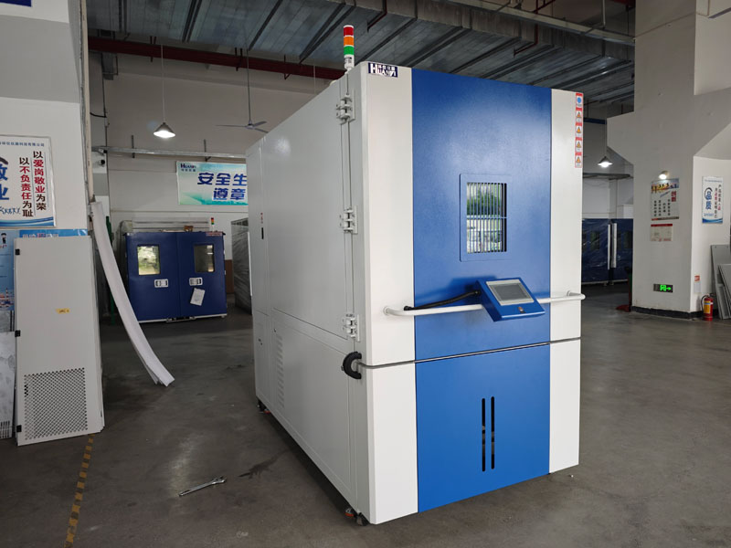
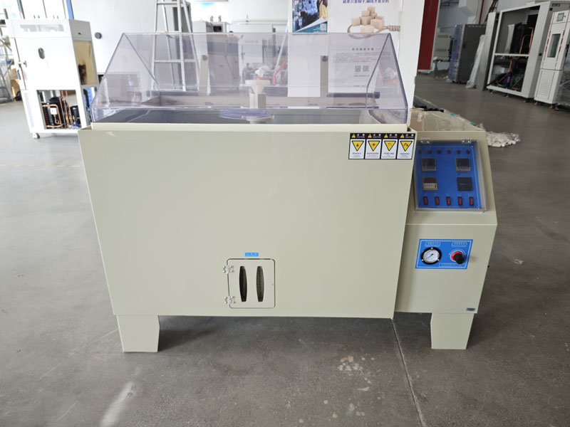
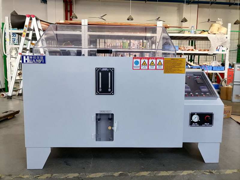
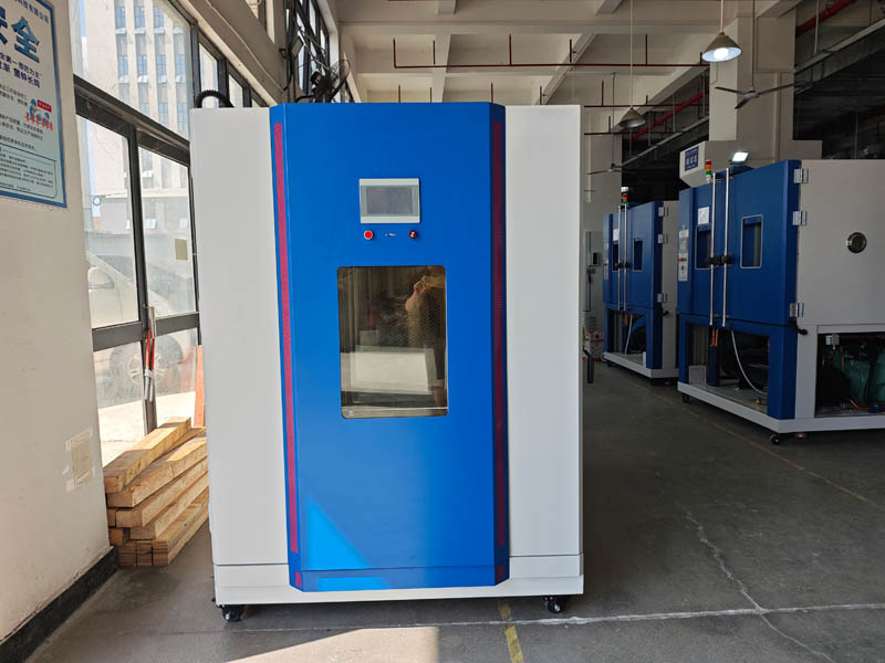
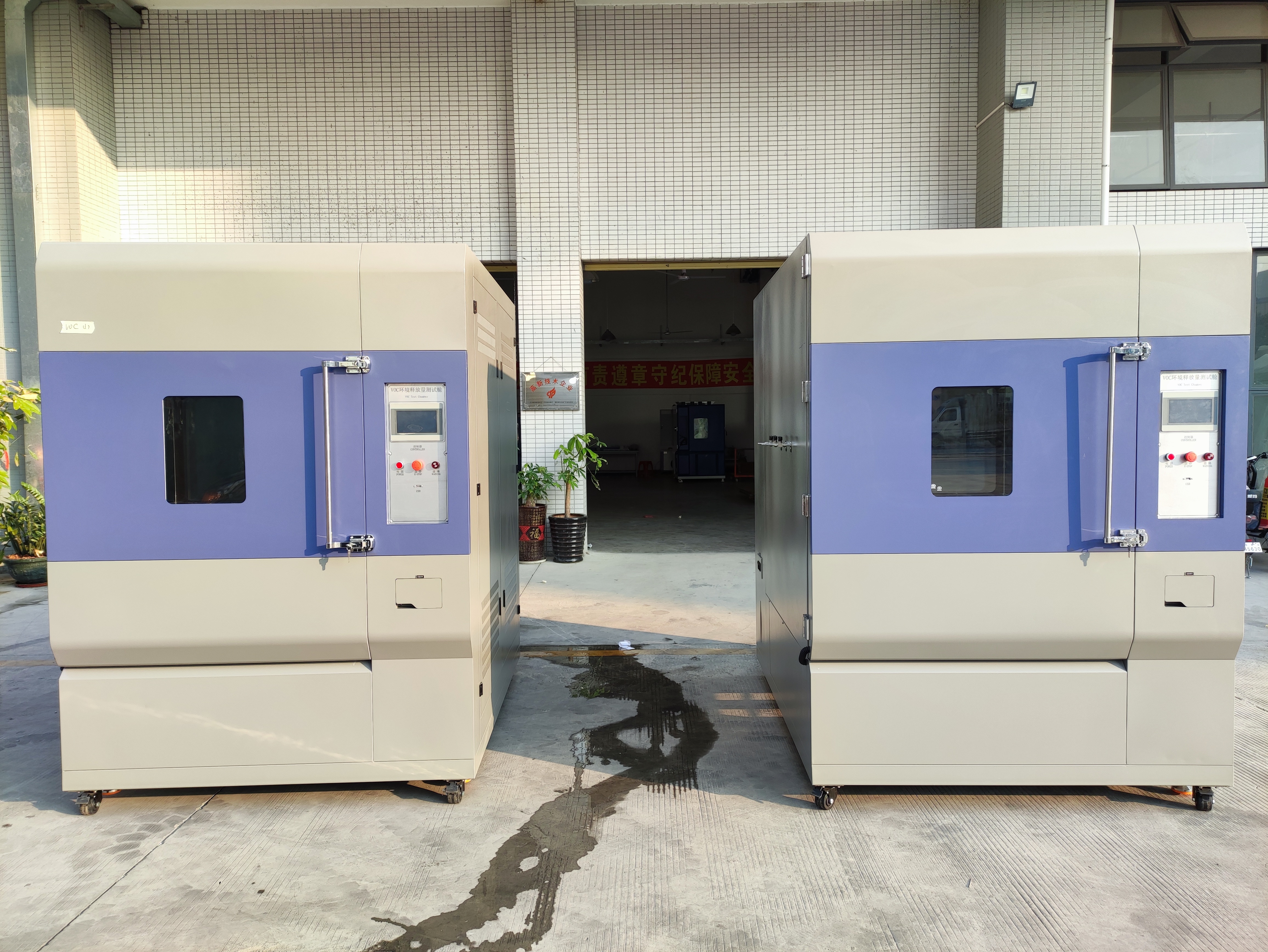
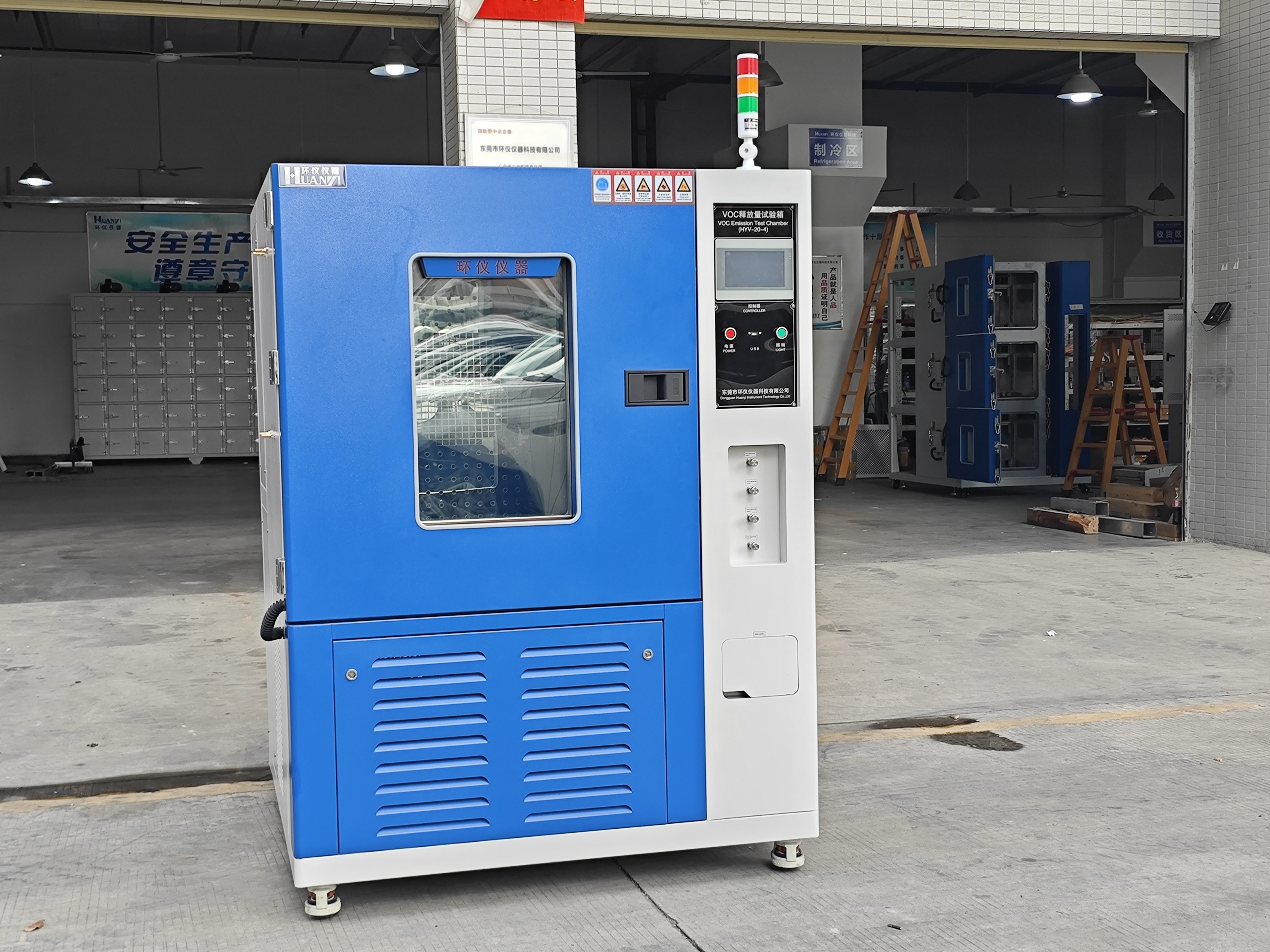
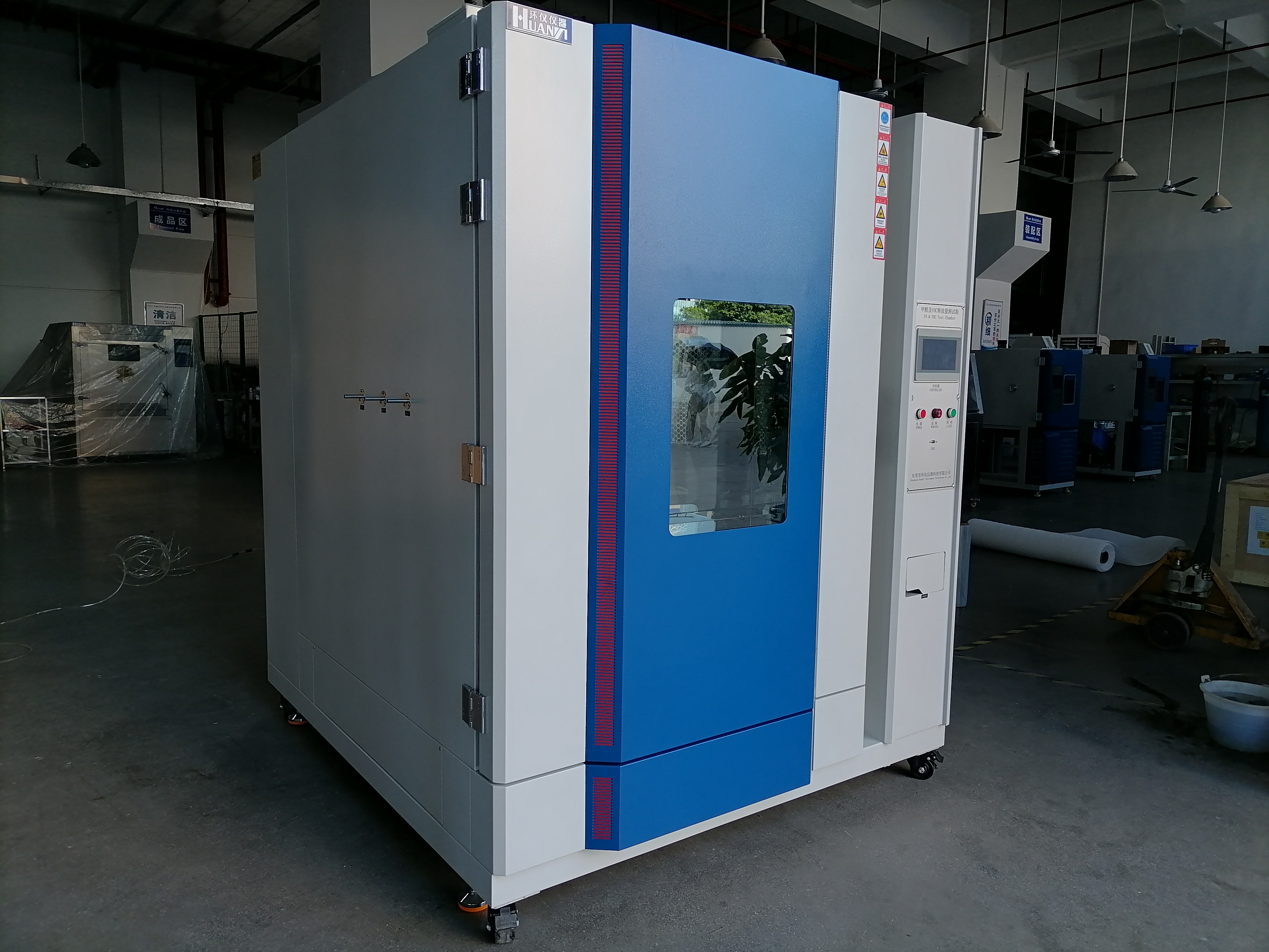
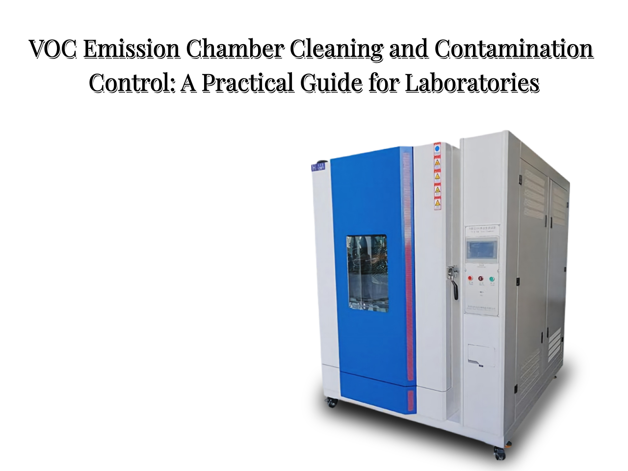
Passive Device Moisture Resistance Cycle Test Chamber
The passive device moisture cycling test chamber meets the standard requirements of GB/T 18310 Basic Test and Measurement Procedures for Fiber Optic Interconnect Devices and Passive Devices Part 2-48: Test Temperature-Humidity Cycling. The test can determine the suitability of fiber optic interconnect devices and passive devices to withstand changes in humidity and temperature that may occur during operation, storage and/or transportation.
Test Objective: To verify the performance of the device after exposure to a humid and hot environment followed by a brief cooling period.
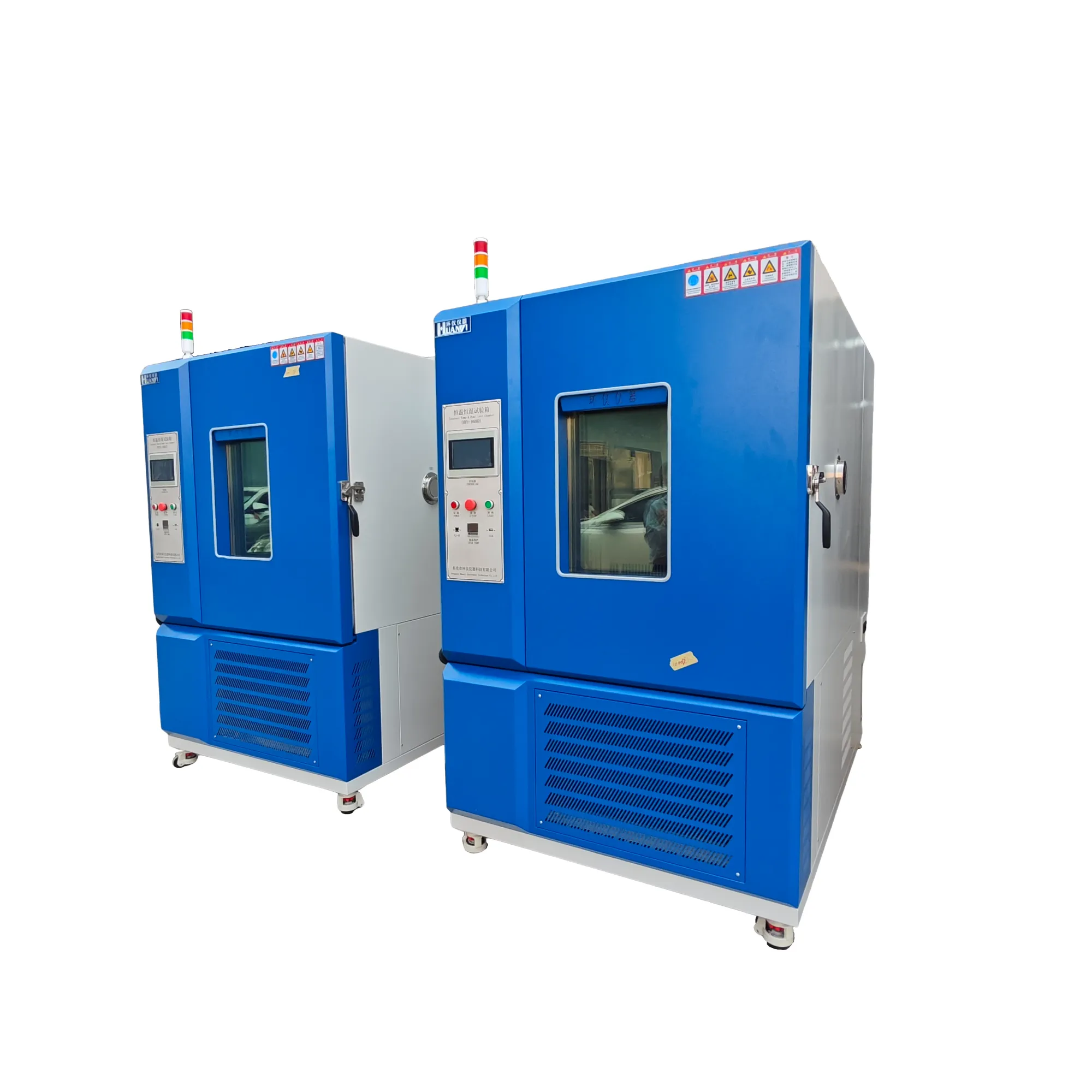
Technical Parameters:
| Brand | Huanyi Instruments | |||
| Temperature Range | 0~150°C | -20~150°C | -40~150°C | -70~150°C |
| Humidity Range | 20%~98%RH | |||
| Temperature and Humidity Fluctuation | ±0.5°C/±2.5%RH | |||
| Temperature and Humidity Uniformity | ≤2°C/≤3%RH | |||
| Temperature and Humidity Deviation | ±2°C, ±3.0%RH (when >75%RH) ±5.0%RH (when ≤75%RH) | |||
| Heating Rate | Approximately 3°C/min (average nonlinear no-load) | |||
| Cooling Rate | Approximately 1°C/min (average nonlinear no-load) | |||
| Inner Casing Material | SUS304 stainless steel | |||
| Outer Casing Material | High-grade steel plate with baked enamel finish or SUS304 stainless steel | |||
| Refrigeration System | Mechanical compressor, binary cascade refrigeration | |||
| Cooling Method | Air-cooled/Water-cooled | |||
| Protective Devices | Leakage protection, compressor overpressure protection, overheat protection, overcurrent protection, over-temperature protection, fan overload protection, phase sequence protection, dry burning/empty combustion protection, and water shortage protection. | |||
| Standard Accessories | One insulated glass viewing window, one test port, two sample racks, one lighting lamp, and a USB interface. | |||
| Remarks | Other studio sizes can be customized to your needs. | |||
Test Conditions:
Adjust the temperature and humidity setting curves of the test chamber to the specified severity level.
The sample should undergo a total of 42 temperature cycles, each cycle from Tmax ± 2℃ to -40℃ ± 2℃, where T is the upper limit temperature specified in the relevant standard (the table below gives several typical values of Tmax). The rate of temperature change should be no less than 1℃/min, and the holding time should be at least 1 hour.
| Temperature range / °C | Humidity range / %RH | Number of cycles |
| -40~85 | 20~85 | 42 |
| -40~70 | 20~85 | 42 |
| -40~65 | 20~85 | 42 |
Note: The insulation temperature should be selected from Tmax, 23℃, and -40℃.
Within the range of 10℃ to Tmax, humidity should be controlled according to the following requirements:
—At 23℃, maintain a constant relative humidity of 85%
—Between 23℃ and Tmax, the relative humidity should change linearly according to the nominal value;
—At Tmax, maintain a constant relative humidity of 20%;
—Between 10℃ and 23℃, maintain a relative humidity of 85%;
—Below 10℃, no relative humidity requirement. However, water vapor in the Environmental Test Chamber should not be discharged; dew and frost are permissible.
The following figure shows a schematic diagram of the temperature-humidity curve when Tmax = 85℃.
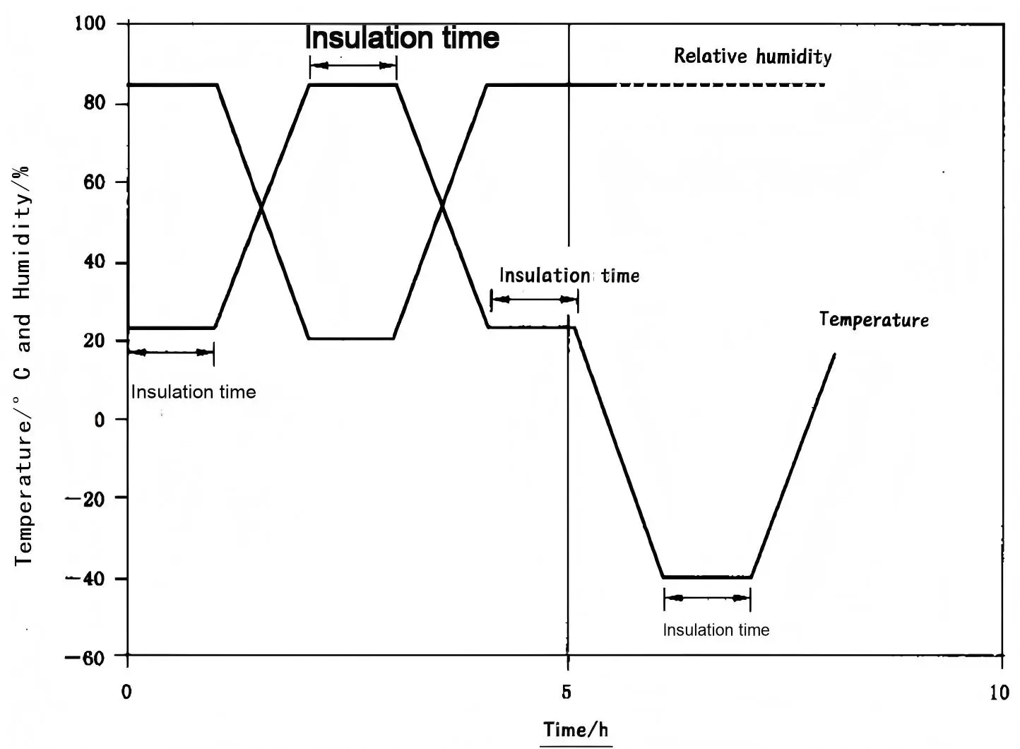
Note: The tolerance for relative humidity is ±5%. This means that in actual operation, relative humidity is allowed to reach 90% for short periods. However, the upper limit for relative humidity in actual measurements is specified as 85%. Attenuation measurements should be performed online throughout the entire test. Attenuation measurements should be within the range specified in the relevant standards.